Smart Mailbox
The goal of this device is to remove the burden of checking the mail everyday by having a mailbox that will let you know when mail arrives. The mailbox detects when a postal worker opens and closes the mailbox. False positives were a concern in our design so in order to counter the false positives we determined it would be fool proof to include a camera. The camera snaps a picture of the mail so the owner could check the attached image in their email and determine if they actually received mail or not.

Demonstration Video
This is a functional demonstration video. The purpose is to show you the operation of the device in a controlled environment. We simulated the door opening and closing by taking the magnet away from the hall effect sensor and then re applying it. You can observe what happens with the Arduino’s and ESP-32’s serial monitor on the left and what’s physically happening on the right.
Circuit and Diagram

Components

The list of components we used are as follow:
Arduino UNO R4
ESP-32 Camera
Hall effect sensor
Breadboard
Magnet
Pull Knob
Mailbox
Wires
Code & I/O Topics
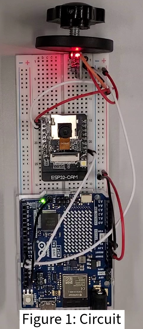
We used an arduino, a hall effect sensor, and an ESP-32 wifi enabled camera to control our mailbox. (see Figure 1: Circuit and Figure 2: Circuit Diagram) The logic controlled by the arduino determines when the door is opened or closed via a hall effect sensor with a loop. (see Figure 5: Arduino Main Loop)
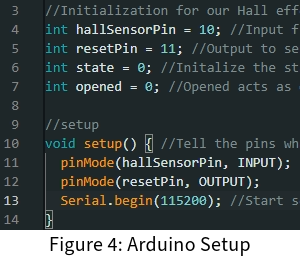
We explored several I/O topics while developing our solution and while troubleshooting. The topics we explored are hall effect and magnetism, coded logic and control signals, image processing, email outputs, and event triggering. We wanted to discuss the most important I/O topics being hall effect and magnetism as our input, and coded logic and control signals as our output. (see Figure 4: Arduino Setup)
The mailbox relies on several components listed above, with the most important components to the concepts we wanted to discuss, being the hall effect sensor, the magnet, the arduino, and the camera. The door of the mailbox has a permanent magnet installed and positioned so that when the mailbox door is opened the hall effect sensor will send a low signal to the Arduino. The hall effect sensor is an A3144 which relies on the hall effect to operate. The hall effect will essentially cause the electrons flowing through a conduit to flow along a specific edge of the conduit which will create a positively charged surface and a negatively charged surface whose orientation depends on the magnet's orientation and current flow. A schmitt trigger inside of the hall effect makes the output signal discrete, or digital, instead of analog with an output of either 0 volts or 5 volts. It is a comparator circuit with hysteresis implemented by applying positive feedback to the noninverting input of a comparator or differential amplifier. A Schmitt Trigger uses two input different threshold voltage levels to avoid noise in the input signal. The action from this dual-threshold is known as hysteresis [8]. Our A3144 requires a south pole to be on the outboard side of the module. The operating point, which is when the output is low, is in the magnetic range of 70 - 350 gauss which is when the door is closed and the magnet is in contact with the sensor. The release point of our sensor is from 50 - 330 gauss which is when the door is opened and the magnet is separated from the sensor which sends a high signal to the arduino [9]. When the Arduino receives a high signal from the hall effect sensor it will then activate a while loop which will continue until it receives a low signal from the hall effect sensor indicating that the door has been closed. (see Figure 5: Arduino Main Loop; lines 19-30) When the Arduino detects the door has been closed it will send a low signal to the camera's reset pin where it will hold that low signal on the pin for 300ms then it will bring it back to high, which resets the camera. (see Figure 5: Arduino Main Loop; lines 31-38) Then the Arduino will return to its initial state of waiting for the door to open. When the camera receives a reset it will run through its code a single time. The camera has onboard programmable wifi capabilities that sends the image it captures to the email provided within its code. (see Figure 6: ESP-32 Email Setup)


Conclusion
We found that the project could have worked with very little components and we went overkill in our design. We learned a lot about Arduino code and troubleshooting, and we learned a lot about designing things and the process we want to use when designing things in the future. The process that we found to work was to come up with the idea and brainstorm possible solutions. In the real world we would want to consider several aspects like cost and production complications, like faulty components etc. If we were to take this concept and attempt to turn it into a product, we would have to simplify it even further, while also making it smarter, like knowing when the owner is retrieving the mail vs the postal worker delivering mail.
Things that didn’t work for us was our lack of delegation. We should have put more effort into delegating responsibilities as opposed to the individual responsibilities falling naturally into place. We had some situations where we were not on the same page about technical aspects, making it difficult to operate as a team. This project, however difficult, was fun, engaging and we learned a lot.